Overview
this first week's lab had to do with basic electronics: how electricity flows, what a parallel vs series circuit is, how to wire up a switch and a variable resistor, etc.
Step 1, Measuring Voltage
after burning through 14 LEDs, i finally got the regulator hooked up correctly. oops.
i had my meter reading 12V for a while, when i checked the voltage between ground and power, until i realised i had my input power (from the battery), going to the wrong 7805 pin. Noob is as Noob does i guess. once i got my power supply plugged into the right place, my multimeter read a re-assuring 5.06V.
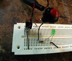
Step 2, A Basic LED Circuit
simple circuit wired with a momentary button.
for this part of this week's assignment, i wired up a basic LED circuit, with a push button, and took voltage measurements across a few points:
switch:
3.8V, off
0V, on
resistor:
0V, off
2.9V, on
LED:
-.4V, off
2.16V, on
The total voltage adds up to 5.06V, when the switch is in the 'on' position, which is just what it should be. Even though circuits aren't supposed to be 100% efficient, this one worked out to be pretty close... within a .01V fluctuation (there was some back n forth going on, with the multimeter reading)
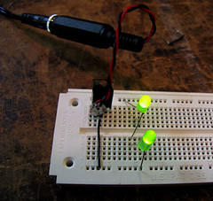
Step 3, Components in Series
LEDs wired in series.
this time, i wired up 2 LEDs, and then a third, in sequential order, on my breadboard. a resistor was not necessary, as each LED acted as a resistor for the next (kind of), by dividing up the voltage accordingly. when i had two LEDs in the board, i measured 2.5V across each of them. once i added a third LED, none of them lit up... this is probably due to the voltage being divided too far, not leaving enough energy for any of the diodes to light up with.
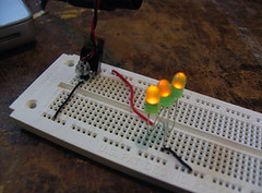
Step 4, Components in Parallel, measuring Amperage
LEDs wired in parallel.
in this instance, i had three LEDs wired up in parallel with each other, giving a voltage reading of 5V across each of them. I couldn't record an amperage reading, unfortunately, as i wasn't able to figure out quite how to take the reading. i'll come back to this later.
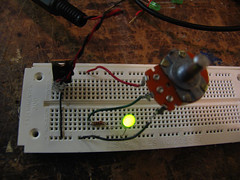
Step 5, Generating a Variable Voltage with a Potentiometer
potentiometer wired to LED
finally, i wired up a potentiometer, which acts as a variable resistor, and lets me change the brightness of my LED since i'm also changing the amount of energy available to it. i put a 220k ohm resistor in place as well, to safeguard against blowing the diode out, when the pot's resistance was down to 0. When the pot was at its center position, i recorded a reading of 1.8V.
*fin*
Subscribe to:
Post Comments (Atom)

No comments:
Post a Comment