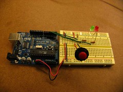
This is my breadboard wired up to an Arduino board, before i plugged it in with a usb cable to my laptop.
This is a simple lab in digital input/output with a microcontroller. The LEDs are wired in series with a momentary button, to the Arduino, which is also delivering 5V to the bread board. I used a simple program for switching between the red and green LED, and uploaded it to my Arduino board with the Arduino IDE.
Pitfalls
At first, I had a 220 resistor in place instead of a 10k resistor.. AND had the power and ground going directly to the button. I could get my red LED to turn on (the default LED that should be on, when the board is first powered), but I could not get my green LED to light up when i pushed the button. Instead, each time I pushed and released my button, the entire Arduino board would restart (which makes sense of course, given how i had initially wired it.
A kindly pcomp soul helped me notice my oversight, however, and all works well now.
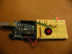
How the board looks when it is plugged in. Nothing too exciting, just a lit up red LED. This is the initial state of the program.
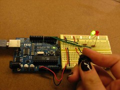
This is what happens after I push the button in. The arduino program sees that the switch value is '1' (i.e., depressed), and cues the green LED to turn on, and the red LED to switch off. hooray.
Subscribe to:
Post Comments (Atom)

No comments:
Post a Comment