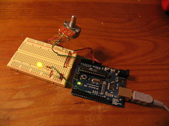
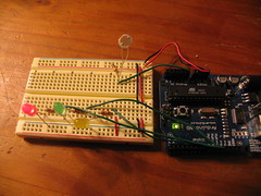
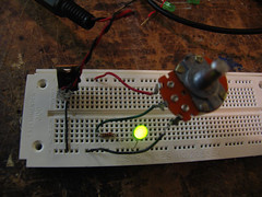
A potentiometer is hooked up to a breadboard, and it's input is read by the arduino board, which outputs it back out from one of it's PWM pins. This simulates analog output, and dims the yellow LED up and down.
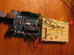
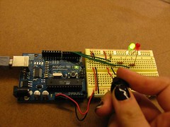
A photocell is hooked up to my breadboard, and its input is read by the arduino board. A photocell basically measures the ambient light, and acts as a resistor according to how much light is entering it. More light is less resistance (i think! ha). Depending on how much light the photocell picks up, one of the three LEDs will light up: yellow for low, green for medium, and red for HIGH! The LEDs are getting their output values from the three PWM pins they are connected to on the arduino board. PWM pins allow for faking analogue output.
When i first programmed the arduino for this, I made the mistake of not dividing the value that i read off the analog-in pin (the one that the photocell is connected to), which resulted in my LEDs jumping up and down, from on to off. This is because I can only output a maximum of 8 bits, or a value of 255, although 10 bits, or a max value of 1023 can be read as input. In order to adjust this, i divided the value read off my analog-in pin by 4.
The jumping from light to dark happens when the output value being sent to the LED goes over 255 (max brightness, and the max value the LED can accept). For every value over 255, the LED will roll back to 0 (off) back up to 255 (fully on). So a value of 256 equals 0, 257 equals 1, 512 equals 0, and so on and so forth.
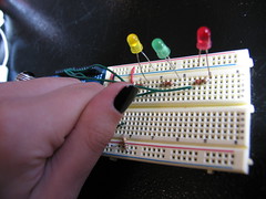
the yellow LED is lit here, showing that a minimum amount of light is hitting the photocell. i'm actually holding the photocell in my hand, in order to block out as much light as i can.
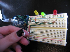
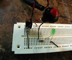
the green LED is lit here, showing that a medium amount of light is hitting the photocell. i'm putting my thumb over the top of the photocell to keep too much light from getting in, for the purpose of this test.
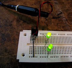
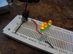
the red LED is lit here, showing that a maximum amount of light is hitting the photocell.
Friday, September 29, 2006
Friday, September 22, 2006
Observation Pt I: General notes
During a typical day, what kinds of digital devices act as a means to an end for us? What are they, and how do we use them?
These are the questions my group and I considered when beginning our observation project, which is divided into two parts. The first part is dealt with in this blog entry.
We spent a couple hours on a Tuesday afternoon, watching people on the streets and in the cafes, pet stores, and shops of new york, hoping to observe their interaction with digital devices.
Links to individual blogs:
Sinan
Maria
Our observations:
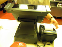
Place: McDonald's on Broadway and Waverly Pl.
Time: 1:30p
Device: cash register
Number of Participants: 1
Process: Tap out a sequence of buttons on the screen. If the customer is paying with cash, go to printing a receipt. Otherwise, customer uses pinpad to swipe plastic card, and on approval, receipt is printed.
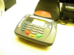
Place: McDonald's on Broadway and Waverly Pl.
Time: 1:30p
Device: pinpad/atm swipe
Number of Participants: 1
Process: Swipe plastic card along side of machine with magnetic strip facing down. Choose if paying with debit or credit. It then shows the amount that will be charged to your card. If debit, enter your pin number on keypad, and hit the green key. Cancel by hitting the red key, and correct a mistake by hitting the yellow key. You are taken through a series of steps, all of which require you to either hit the yellow key for correction, red key for cancel, green key for ok/enter.
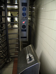
Place: NQRW subway station @ Broadway and 8th Street
Time: 1:38p
Device: metrocard swipe
Number of Participants: 1
Process: Push card through card reader with one movement, away from you. Stripe must be facing down and to the right. Green arrow/red 'X' indicates success or failure. If it's a success, you can enter the turnstyle and be on your way.
Place: Street at 3rd Avenue and 8th Street
Time: 1:45p
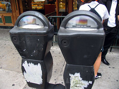
Device: parking meter
Number of Participants: 1
Process: Parking meter has a slot for coins on the front side, and on the back side, displays an indicator color, red or green, to show whether or not time is still on the meter or not.
Place: Bamn! Automat on 10th Street between 2nd and 3rd Ave
Time: 2:11p
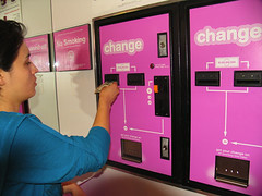
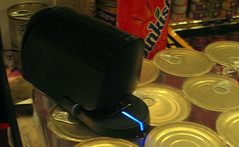
Device: change maker
Number of Participants: 1
Process: A change maker at a restaurant, provides $1 coins in exchange for paper money and smaller coins. You put your paper money or coins into the appropriate slot, and at the bottom of the machine, dollar coins are dropped according to how much money you originally put in.
Place: Bamn! Automat on 10th Street between 2nd and 3rd Ave
Time: 2:13p
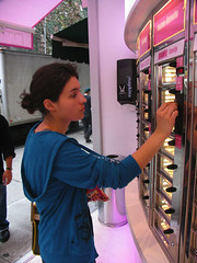
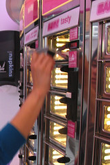
Device: vending machine unit
Number of Participants: 1
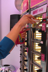
Process: Each vending machine unit has a slot to receive money, and a slot to return money. There is also a white button that will return your money to you, if you push it. Above the coin slots is a screen which displays how much money you have put in so far. To the left of the display and the coin slots, is a glass door, which opens from pull down, after enough money has been put in to pay for the item. At this point, you remove the food from the space behind the door, and release the door after you have taken it out.
Place: Whisker's Pet Store on 10th Street between 1st and 2nd Ave
Time: 2:29p
Device: electronic stapler
Number of Participants: 1
Process: Put whatever you are trying to staple, into the device, as you would with a non-electrical stapler. Some kind of sensor detects the paper there, and drives a staple through the sheets. Takes about a quarter second to complete the action.
Place: Starbuck's Cafe on 2nd Avenue
Time: 2:43p
Device: cell phone
Number of Participants: 1
Process: Pick up phone, dial a number using the keypad. Hold phone up to your ear to listen and talk.
Place: Starbuck's Cafe on 2nd Avenue
Time: 2:43p
Device: laptop
Number of Participants: 2
Process: Two people were leaning over one laptop. Most of the time was spent gazing at the screen, with a track pad button clicks, and finger tracings around the pad itself.
Place: Outside Starbuck's Cafe on 2nd Avenue
Time: 3:00p
Device: bluetooth wireless device - goes in ear
Number of Participants: 1
Process: Bluetooth hands-free device hooks into ear. Apparently, you can answer phone calls, and hear and be heard over this thing. Not much is involved in the process, other than talking and listening.
These are the questions my group and I considered when beginning our observation project, which is divided into two parts. The first part is dealt with in this blog entry.
We spent a couple hours on a Tuesday afternoon, watching people on the streets and in the cafes, pet stores, and shops of new york, hoping to observe their interaction with digital devices.
Links to individual blogs:
Sinan
Maria
Our observations:
Place: McDonald's on Broadway and Waverly Pl.
Time: 1:30p
Device: cash register
Number of Participants: 1
Process: Tap out a sequence of buttons on the screen. If the customer is paying with cash, go to printing a receipt. Otherwise, customer uses pinpad to swipe plastic card, and on approval, receipt is printed.
Place: McDonald's on Broadway and Waverly Pl.
Time: 1:30p
Device: pinpad/atm swipe
Number of Participants: 1
Process: Swipe plastic card along side of machine with magnetic strip facing down. Choose if paying with debit or credit. It then shows the amount that will be charged to your card. If debit, enter your pin number on keypad, and hit the green key. Cancel by hitting the red key, and correct a mistake by hitting the yellow key. You are taken through a series of steps, all of which require you to either hit the yellow key for correction, red key for cancel, green key for ok/enter.
Place: NQRW subway station @ Broadway and 8th Street
Time: 1:38p
Device: metrocard swipe
Number of Participants: 1
Process: Push card through card reader with one movement, away from you. Stripe must be facing down and to the right. Green arrow/red 'X' indicates success or failure. If it's a success, you can enter the turnstyle and be on your way.
Place: Street at 3rd Avenue and 8th Street
Time: 1:45p
Device: parking meter
Number of Participants: 1
Process: Parking meter has a slot for coins on the front side, and on the back side, displays an indicator color, red or green, to show whether or not time is still on the meter or not.

Place: Bamn! Automat on 10th Street between 2nd and 3rd Ave
Time: 2:11p
Device: change maker
Number of Participants: 1
Process: A change maker at a restaurant, provides $1 coins in exchange for paper money and smaller coins. You put your paper money or coins into the appropriate slot, and at the bottom of the machine, dollar coins are dropped according to how much money you originally put in.
Place: Bamn! Automat on 10th Street between 2nd and 3rd Ave
Time: 2:13p
Device: vending machine unit
Number of Participants: 1
Process: Each vending machine unit has a slot to receive money, and a slot to return money. There is also a white button that will return your money to you, if you push it. Above the coin slots is a screen which displays how much money you have put in so far. To the left of the display and the coin slots, is a glass door, which opens from pull down, after enough money has been put in to pay for the item. At this point, you remove the food from the space behind the door, and release the door after you have taken it out.
Place: Whisker's Pet Store on 10th Street between 1st and 2nd Ave
Time: 2:29p
Device: electronic stapler
Number of Participants: 1
Process: Put whatever you are trying to staple, into the device, as you would with a non-electrical stapler. Some kind of sensor detects the paper there, and drives a staple through the sheets. Takes about a quarter second to complete the action.
Place: Starbuck's Cafe on 2nd Avenue
Time: 2:43p
Device: cell phone
Number of Participants: 1
Process: Pick up phone, dial a number using the keypad. Hold phone up to your ear to listen and talk.
Place: Starbuck's Cafe on 2nd Avenue
Time: 2:43p
Device: laptop
Number of Participants: 2
Process: Two people were leaning over one laptop. Most of the time was spent gazing at the screen, with a track pad button clicks, and finger tracings around the pad itself.
Place: Outside Starbuck's Cafe on 2nd Avenue
Time: 3:00p
Device: bluetooth wireless device - goes in ear
Number of Participants: 1
Process: Bluetooth hands-free device hooks into ear. Apparently, you can answer phone calls, and hear and be heard over this thing. Not much is involved in the process, other than talking and listening.
Wednesday, September 20, 2006
'Conceptual Blockbusting'
The title of this blog entry comes from the name of a book I read an excerpt from, by James L. Adams. The basic idea was that, we cloud our vision by prejudices that come out of stereotypes that we hold for different kinds of people and situations. When approaching a situation with most of the information pre-determined, we lose the ability to form honest, valid opinions about others or the problem at hand.
This can lead to us imposing more than social limitations on ourselves.. it can also affect our ability to be effective problem solvers. If we approach any kind of problem from this point of view, be it getting to know someone, or trying to figure out why a computer program is buggy, we risk missing a lot of elegant solutions. In other words, we restrict our creativity, which is largely our ability to put together disparate ideas. Creativity in problem solving often leads to innovative and inspired solutions, so clearly it would be a shame to do anything to hinder this.
He mentions another author in his book: Edward De Bono. I was pretty happy about this, as De Bono is one of my favorite authors on the subject of creative thinking. De Bono has a book out which, I can recommend highly, and is also referenced in Adams' writing, called Lateral Thinking. It touches on points that Adams discusses, and has been singularly important in helping me break out of my own bad thinking/perception habits.
lab: week 2, 1st Arduino program
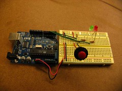
This is my breadboard wired up to an Arduino board, before i plugged it in with a usb cable to my laptop.
This is a simple lab in digital input/output with a microcontroller. The LEDs are wired in series with a momentary button, to the Arduino, which is also delivering 5V to the bread board. I used a simple program for switching between the red and green LED, and uploaded it to my Arduino board with the Arduino IDE.
Pitfalls
At first, I had a 220 resistor in place instead of a 10k resistor.. AND had the power and ground going directly to the button. I could get my red LED to turn on (the default LED that should be on, when the board is first powered), but I could not get my green LED to light up when i pushed the button. Instead, each time I pushed and released my button, the entire Arduino board would restart (which makes sense of course, given how i had initially wired it.
A kindly pcomp soul helped me notice my oversight, however, and all works well now.
How the board looks when it is plugged in. Nothing too exciting, just a lit up red LED. This is the initial state of the program.
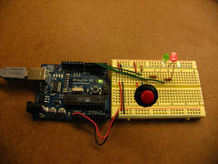
This is what happens after I push the button in. The arduino program sees that the switch value is '1' (i.e., depressed), and cues the green LED to turn on, and the red LED to switch off. hooray.
This is a simple lab in digital input/output with a microcontroller. The LEDs are wired in series with a momentary button, to the Arduino, which is also delivering 5V to the bread board. I used a simple program for switching between the red and green LED, and uploaded it to my Arduino board with the Arduino IDE.
Pitfalls
At first, I had a 220 resistor in place instead of a 10k resistor.. AND had the power and ground going directly to the button. I could get my red LED to turn on (the default LED that should be on, when the board is first powered), but I could not get my green LED to light up when i pushed the button. Instead, each time I pushed and released my button, the entire Arduino board would restart (which makes sense of course, given how i had initially wired it.
A kindly pcomp soul helped me notice my oversight, however, and all works well now.
How the board looks when it is plugged in. Nothing too exciting, just a lit up red LED. This is the initial state of the program.
This is what happens after I push the button in. The arduino program sees that the switch value is '1' (i.e., depressed), and cues the green LED to turn on, and the red LED to switch off. hooray.
Monday, September 18, 2006
Nature of Code - week 1
Some interesting points I came across in The Computational Beauty of Nature, by Gary Flake...
Flake talks about a few different ways in which we might describe a 'thing'. This could be an animal, an atom, or any other constituent of a larger system. According to him, there are three main ways in which we can begin to understand how these things work:
- Look at the 'thing' in question, called an 'agent', isolated from its environment. Dissect it and try to understand how it works and behaves as an individual.
- Look at the system in which it exists from a global point of view, observing the overall pattern formed by all of the system's agents.
- Look at the interactivity between the agents within the global system, or environment, which is akin to taking the middle road. This is the preferred path to take in trying to really understand how an agent works.
It would only be a fraction of the story, to look at one agent individually, observing its separate parts and functions in a vacuum. To really get a good idea, Flake suggest that we need to consider how these agents interact with each other, and therefore within their environment.. how do they respond to one another, and deal with each other on a routine basis? What aspects of the environment are they interacting with, and how can these actions be described?
These thoughts also relate to how we can come to understand a system as a whole. It's possible to go from a larger scope, to smaller one, i.e. take the 'reductionist' point of view, when trying to describe an environment. This is basically, starting at the most general level of things (for example, the universe), and working your way back down to the smallest unit (like perhaps, a proton).
However, it doesn't really work going the other direction. Knowing what an atom is, isn't going to help you in figuring out that it exists in a molecule, in a cell, in the muscle fiber of an animal, etc.
The other point of view one can take is the exact opposite of reductionism, which is holism. In holism, the sum of the parts is greater than the individual parts themselves.
Another concept brought up by Flake is the idea of 'adaptation'. According to him, parallelism + multiplicity = adaptation. Parallelism is having multiple threads going of a similar action, whereas multiplicity is having multiple threads going of different actions, but which are trying to solve the same problem. Multiplicity produces subtle variations among agents in a system, and paves the way for evolution. There will be more successful solutions than others, and the most successful will have the greater chance of survival and reproduction, or 'iteration'.
Going back to interaction, Flake points out that the simplest type of question we can ask when considering this between two agents, X and Y, is, what will 'X' do in the presence of 'Y'?
That's all for now, but i have also posted two processing examples below. These, by the way, have nothing to do with what I just mused over. These are just two examples showing the visual difference between uniform and non-uniform probability. The uniform example is first.
uniformly random lines
non-uniformly random lines
Sunday, September 17, 2006
reaction vs interaction
the idea of reaction vs interaction, is one which is going to help me a lot while i try to develop 'interactive' projects now and in the future. it is a point brought up within the first two chapters of 'The Art of Interactive Design', by Chris Crawford. basically, according to mr. crawford, for something to be interactive, it must meet three points successfully: 1. it must accept an input, 2. process the information received through the input, and 3. formulate some kind of response, or output.
previously, i felt that if anything responded to you in any manner whatsoever, it could qualify as being 'interactive'. however, after thinking about the differences between reaction versus interaction, i realised that just because something delivers a response, does not mean that it did so by means of any kind of meaningful process. for example, if you sit on a chair, it will hold you up, exerting a force against your body (providing it can support your weight), regardless of any other circumstances regarding the event. however, if you sit on a person, they'll either be startled, or maybe laugh, or have no response at all. it depends on the context in which the event took place, and even though most of us would be weirded out by someone sitting on us, it's conceivable that there are circumstances in which it wouldn't be that strange (for example, in a crowded car, when it's necessary to play musical laps to fit 6 people in the backseat). this is a much more interactive event, by definition, because there is an array of responses available for a single kind of input.
anyways, it's definitely something worth thinking about.
lab: week 1
Overview
this first week's lab had to do with basic electronics: how electricity flows, what a parallel vs series circuit is, how to wire up a switch and a variable resistor, etc.
Step 1, Measuring Voltage
after burning through 14 LEDs, i finally got the regulator hooked up correctly. oops.
i had my meter reading 12V for a while, when i checked the voltage between ground and power, until i realised i had my input power (from the battery), going to the wrong 7805 pin. Noob is as Noob does i guess. once i got my power supply plugged into the right place, my multimeter read a re-assuring 5.06V.
Step 2, A Basic LED Circuit
simple circuit wired with a momentary button.
for this part of this week's assignment, i wired up a basic LED circuit, with a push button, and took voltage measurements across a few points:
switch:
3.8V, off
0V, on
resistor:
0V, off
2.9V, on
LED:
-.4V, off
2.16V, on
The total voltage adds up to 5.06V, when the switch is in the 'on' position, which is just what it should be. Even though circuits aren't supposed to be 100% efficient, this one worked out to be pretty close... within a .01V fluctuation (there was some back n forth going on, with the multimeter reading)
Step 3, Components in Series
LEDs wired in series.
this time, i wired up 2 LEDs, and then a third, in sequential order, on my breadboard. a resistor was not necessary, as each LED acted as a resistor for the next (kind of), by dividing up the voltage accordingly. when i had two LEDs in the board, i measured 2.5V across each of them. once i added a third LED, none of them lit up... this is probably due to the voltage being divided too far, not leaving enough energy for any of the diodes to light up with.
Step 4, Components in Parallel, measuring Amperage
LEDs wired in parallel.
in this instance, i had three LEDs wired up in parallel with each other, giving a voltage reading of 5V across each of them. I couldn't record an amperage reading, unfortunately, as i wasn't able to figure out quite how to take the reading. i'll come back to this later.
Step 5, Generating a Variable Voltage with a Potentiometer
potentiometer wired to LED
finally, i wired up a potentiometer, which acts as a variable resistor, and lets me change the brightness of my LED since i'm also changing the amount of energy available to it. i put a 220k ohm resistor in place as well, to safeguard against blowing the diode out, when the pot's resistance was down to 0. When the pot was at its center position, i recorded a reading of 1.8V.
*fin*

Subscribe to:
Posts (Atom)